Flash-X is a component based software system where different
permutations and combinations of various components generate different
applications. Some aspects of Flash-X architecture are adapted from
FLASH , but it is fundamentally a new software with an architecture
designed for use with heterogeneous platforms. Portability on
heterogeneous platforms is achieved through
a new orchestration system for applications (ORCHA) that is
designed to be language agnostic and adaptable for future changes in
the computing platforms. ORCHA has a collection of tools that address
three main major concerns from the applications perspective described
below.
As mentioned earlier Flash-X is not a monolithic application code;
instead, it should be viewed as a collection of components that are
selectively grouped to form various applications. Users specify which
components should be included in a simulation, define a rough
discretization/parallelization layout, and assign their own initial
conditions, boundary conditions, and problem setup to create a unique
application executable. In Flash-X terminology, a component that
implements an exclusive portion of the code’s functionality is called
a unit. A typical Flash-X simulation requires a proper subset of the
units available in the code. Thus, it is important to distinguish
between the entire Flash-X source code and a given Flash-X
application.
A Flash-X unit provides well-defined functionality and publishes an
Application Programming Interface (API), a collection of routines
through which other units can interact with it. A unit
can have multiple alternative implementations of varying complexity
and for different purposes. A unit can have an arbitrary number of
subunits that provide subsets of the unit’s functionality, though in
practice the number of subunits remains low. Units must include a null
implementation for every routine in their API at the top level of
their hierarchy. This feature permits an application to
easily exclude a unit without the need to modify code elsewhere. For
example, the input/output unit can be easily turned on and off for
testing purposes, by using the null implementations.
Flash-X implements its inheritance, extensibility, and
modularity through its configuration layer. This layer
consists of a collection of text Config files that reside at various
levels of the code organization, and the setup tool which interprets
the Config files. The two primary functions of this layer are to
configure a single application from the Flash-X source tree, and to
implement inheritance and customizability in the code.
Unit architecture abstracts the computational complexity of
the unit from its public interfaces, and controls the scope of various
data items owned by the unit. A unit’s API provides interfaces for
modifying the state of the solution and for accessing and modifying
data it owns that may be needed by other units.
Units can have one or more subunits which are groupings of
self-contained functionality. The concept subunits
formalizes the selective use of a subset of a unit’s functionality,
and the possibility of multiple alternative implementations of the
same subset. Subunits implement disjoint subsets of a
unit’s API, where none of the subsets can be a null set. The union of
all subsets constituting various subunits must be exactly equal to the
unit API. Every unit has at least a Main subunit that implements the
bulk of the unit’s functionality, including its initialization. The
Main subunit is also the custodian of all the unit-scope data.
Subunits and other finer-grained components can have their own data
modules that are only visible to the routines and functions within
those components. In other words, a data module placed in a directory
is only visible to routines in functions in that directory or its
sub-directories, but not to its parent or ancestor directories.
Flash-X inheritance is implemented through the Unix directory structure
and the setup tool. When the setup tool parses the source tree, it
treats each child or subdirectory as inheriting all of the Config and
Makefile files in its parent’s directory. While source files at a given
level of the directory hierarchy override files with the same name at
higher levels, Makefiles and configuration files are cumulative. Since
functions can have multiple implementations, selection for a specific
application follows a few simple rules described in the following
Figures.
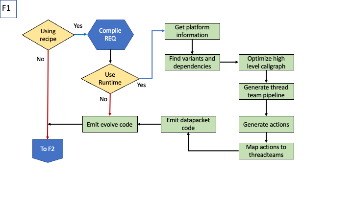
Overview of the control flow during configuration
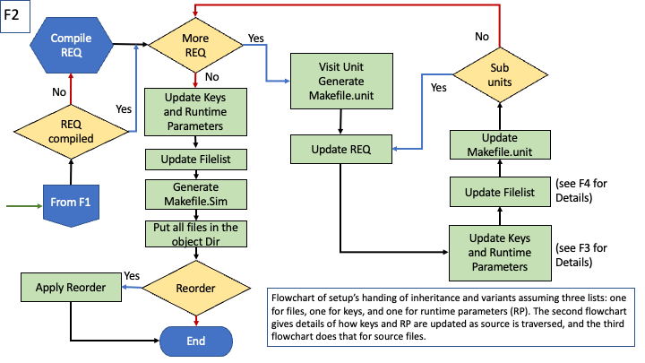
Overview of the inheritance in various components of the code
Overview of the control flow during configuration
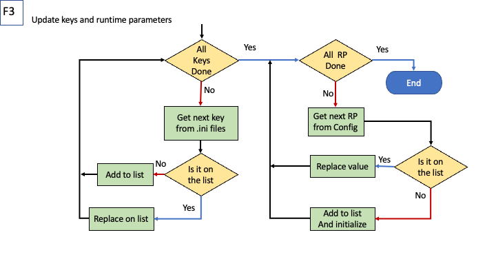
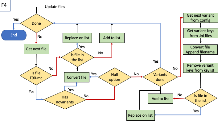
Steps in arbitration on files to be included/generated
However, we must take care that this special use of the directory
structure for inheritance does not interfere with its traditional use
for organization. We avoid any problems by means of a careful naming
convention that allows clear distinction between organizational and
namespace directories. See for naming conventions.
The Simulation unit in the code is treated differently from all other
units because this is where the application is defined. The parsing of
Config file begins from that of the application being
configured. Additionally, this unit also provides the mechanism for
customization. The inheritance implemented by the setup tool
replaces any file or a macro definition assembled during the
configuration of hte application if another file or macro of the same
name is encountered in the Simulation unit. Thus a user desirous of
customizing any part of the source code can do so by simply placing an
identically named file or macro in a file with “.ini” extenstion in
the directory that they created for their Simulation.
In keeping with good software practice, Flash-X incorporates a unit test
framework that allows for rigorous testing and easy isolation of errors.
The components of the unit test show up in two different places in the
Flash-X source tree. One is a dedicated path in the Simulation unit,
Simulation/SimulationMain/unitTest/UnitTestName, where
UnitTestName is the name of a specific unit test. The other place is a
subdirectory called unitTest, somewhere in the hierarchy of the
corresponding unit which implements a function Unit_unitTest and any
helper functions it may need. The primary reason for organizing unit
tests in this somewhat confusing way is that unit tests are special
cases of simulation setups that also need extensive access to internal
data of the unit being tested. By splitting the unit test into two
places, it is possible to meet both requirements without violating unit
encapsulation. We illustrate the functioning of the unit test framework
with the unit test of the Eos unit. For more details please see .
The Eos unit test needs its own version of the routine
Driver/Driver_evolveAll which makes a call to its Eos_unitTest
routine. The initial conditions specification and unit test specific
Driver_evolveAll are placed in
Simulation/SimulationMain/unitTest/Eos, since the Simulation
unit allows any substitute Flash-X function to be placed in the specific
simulation directory. The function Eos_unitTest resides in
physics/Eos/unitTest, and therefore has access to all internal
Eos data structures and helper functions.